
|
About Us
|
 |
 |
 |
 |
 |
Airflow Testing of Carburetors
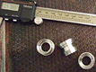
 Airflow testing of a carburetor consists of two measurements. First is the airflow itself, measured in cubic feet per minute (CFM). Second is the vacuum under the carb that pulls the air through the carb. This vacuum is more technically called the pressure drop, and is measured in inches of water with a device called a manometer. The scientific name for this pressure drop is delta P. The standard delta P for rating 4 barrel carb airflow is 1.5 inches of mercury (1.5" Hg), which is equal to 20.4 inches of water (20.4" H2O). An airflow test simply consists of installing the carb onto the airflow bench with an appropriate adapter, holding the throttles wide open, raising the airflow until the delta P equals 20.4" H2O, and reading the airflow amount. Yes, but it isn't that simple.
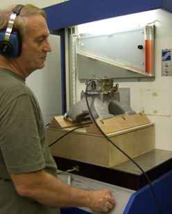
Measuring the airflow is the easy part. Measuring the delta P accurately is more challenging. The vacuum probe in the flowbench that measures the delta P is supposed to measure just the vacuum. A poor choice of the type of probe used, and/or the poor placement of the probe in the flowbench, can allow the probe to be affected by air velocity and air turbulence, making the delta P reading from the probe inaccurate and unstable. This inaccurate delta P reading, in turn, makes the airflow reading inaccurate, and depending on the direction of air velocity and turbulence around the probe, the airflow reading can be dramatically higher or lower than the real airflow. The stock delta P probe in my Superflow 300 bench was seriously affected by air velocity and turbulence around the probe. So I replaced it with a different type of probe in a different location, and now the delta P reading is much less affected by air velocity and turbulence.
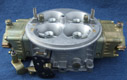
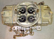
 Testing with the new delta P probe and different carb to flowbench adapters still gave surprisingly different airflow results with the same carb. It became evident that the pressure recovery varied greatly from one adapter to another. When a carb flows air into a cavity (an adapter or a manifold plenum), the air recovers most of the pressure that it had when it was above the carb. The extent of this pressure recovery is determined by the airflow characteristics of the carb, the carb spacer (if used), and the intake manifold. Higher pressure recovery means that the air has transitioned smoothly from the carb to the manifold runners. If all of the changes in airflow direction can be achieved with a minimum of turbulence, then the total airflow will be higher, helping the engine make more power. The large variation in pressure recovery also brought up another question. How does the pressure recovery of any of these carb adapters on the flowbench compare to an actual racing intake manifold?
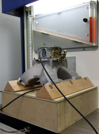
To answer this question, I built a carburetor flow fixture that incorporates a single plane small block Chevrolet intake commonly used on 700 HP oval track engines. A new style delta P probe is used to measure plenum vacuum, and another is used to measure the vacuum drawing air through the ports of the manifold. As I had suspected, the pressure recovery of the manifold is better than some of the adapters I used before, and worse than others. My standard test for total carb airflow now consists of measuring airflow on an adapter that has really good pressure recovery... pressure recovery that you would see with a really good, professionally ported, single plane intake. That way, carb and carb spacer airflow development will show improvements,positive OR negative, and not be masked by the ability of the flow bench adapter to flow and allow good pressure recovery. © Norm Schenck/CFS